Embedded Processing & Memory
Showing the single result
From£3.20(Ex. VAT)
Enquire for availability
Make an Enquiry
Alliance Memory - AS6Cxxxx Series SRAM
XProduct SKU: AS6C1008-55PCN-P
The AS6C1008 is a 1,048,57 6-bit low power CMOS static random access memory organized as 131,072 words by 8 bits. It is fabricated using very high performance, high reliability CMOS technology. Its standby current is stable within the range of operating temperature. The AS6C1008 is well designed for very low power system applications, and particularly well suited for battery back-up non-volatile memory application. The AS6C1008 operates from a single power supply of 2.7V ~ 5.5V.
CONTACT US FOR VOLUME PRICING
Enquire for availability
Make an Enquiry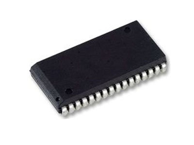
Alliance Memory - AS7C3xxx Series 3V SRAM
XProduct SKU: AS7C31025B-12JIN-P
The AS7C31025B is a high-performance CMOS 1,048,576-bit Static Random Access Memory (SRAM) device organized as 131,072 x 8 bits. It is designed for memory applications where fast data access, low power, and simple interfacing are desired.
CONTACT US FOR VOLUME PRICING
Enquire for availability
Make an Enquiry
Alliance Memory - AS7Cxxx Series 5V SRAM
XProduct SKU: AS7C1024B-12JCNPBF-P
The AS7C1024B is a high performance CMOS 1,048,576-bit Static Random Access Memory (SRAM) device organized as 131,072 words x 8 bits. It is designed for memory applications where fast data access, low power, and simple interfacing are desired.
CONTACT US FOR VOLUME PRICING
Enquire for availability
Make an Enquiry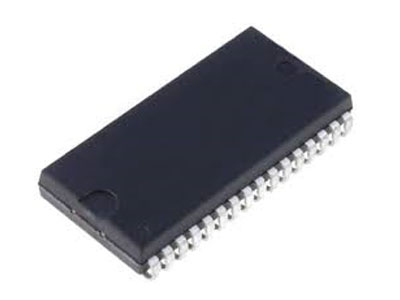
AMIC Technology - A62xxxx Series Low Power SRAM
XProduct SKU: A623308A-70SF-P
The A623308A is a low operating current 65,536-bit static random access memory organized as 8,192 words by 8 bits and operates on a voltage from 4.5V to 5.5V. Inputs and three-state outputs are TTL compatible and allow for direct interfacing with common system bus structures. Minimum standby power is drawn by this device when CE is at a high level, independent of the other input levels. Data retention is guaranteed at a power supply voltage as low as 2.0V.
CONTACT US FOR VOLUME PRICING
Enquire for availability
Make an Enquiry
From£2.00(Ex. VAT)
Holtek Charger Flash MCU HT45F5Q-2
XProduct SKU: HT45F5Q-2 20SOP
For AC/DC charger applications, the Charger ASSP Flash MCU HT45F5Q-2 includes a battery charger management module, which can be used for the constant voltage and constant current closed loop charging control. The device therefore reduces the need for the usually required external TL431 component, operational amplifier and resistance analogic D/A Converter in traditional battery charging circuits. Therefore the peripheral circuit is more reduced, resulting in a smaller PCB area. The charger management module is composed of two parts. The first part contains two groups of OPAs and D/A Converters, which are used to control the charging voltage and current. The upper limit value of the charger constant voltage and constant current can be obtained by configuring the D/A Converters in the software. The 12-bit D/A Converter is used for constant voltage control while the 8-bit D/A Converter is used for constant current control. The second part of the charger management contains a fixed gain operational amplifier which is used for current amplification. This improves the current resolution and allows the use of smaller current detection resistors thus reducing the resistor power consumption. The D/A Converter in the charger management module is not only used for setting charging voltage and current, but also can be used together with the specific charger production fixtures for improving the traditional manual calibration techniques. By using the external production fixtures, the charger current voltage/current conditions can be confirmed. If the margin of errors is exceeded, the MCU will correct the error by fine tuning the D/A Converter, and store the corrected parameters to EEPROM. When the charger is recharged, the D/A Converter will be given a new correction value to implement correction purpose. Refer to the Holtek application notes for more details.
From£2.00(Ex. VAT)
Enquire for availability
Make an Enquiry